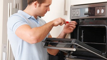
I have a GE stove, need to change door springs how do you remove the tracks from bottom draw to gain access to little door to change spring any help would be appreciated thank you
- James Buchanan asked 10 years ago
Here is the only information we have on this unit. Hope it helps.
lower, left hand rear corner of the range as viewed
from the front.
a) Depending on the model, remove the storage
drawer, broiler drawer or false panel to access the
regulator. Some models with a broiler drawer will have
a metal cover over the regulator that must be removed
for conversion and reinstalled when conversion is
complete.
b) Remove the Large hex-nut which is located in the
center of the regulator. Remove the plastic pin from the
bottom side of the cap, turn the pin 180 degrees and
snap the pin back into the cap. There are raised letters
on the flat side of the plastic pin, “NAT” and “LP”. In the
“LP” position the end of the pin marked “NAT” should be
snapped into the bottom of the hex-nut.
CONVERSION TO LP (PROPANE) GAS
4. Check quality of the flames
The combustion quality of the burner flames needs
to be determined visually.
NOTE: If burner flames look like (A). Further air
shutter adjustment is required. Normal burner
flames should look like (B) or (C), depending on
the type of gas you use. With LP gas, some
yellow tipping on the outer cones is normal.
(A) Yelow Flames:
Further Adjustment
Required
B) Yellow tips on
outer cones:
Normal for LP Gas
(C) Soft Blue flames:
Normal for Natural Gas.
Color coding is used in identifying the correct location.
e) The prevent leakage, make sure the orifice spuds
are securely screwed into the gas supply tubes.
f) Install the old NG orifice spuds into the metal
bracked and place back on the range for possible
2. Converting the surface burners future conversion.
a) LP orifice spuds are located at the back of the storage/
broiler drawer compartment. The spud are in a metal
bracket next to the pressure regulator and are attatched
to the back wall of the compartment by a 1/4″ hex head
screw. An LP conversion instruction sheet is also
located in this area. (see above picture)
b) Removed grates, burner caps, and burner heads.
c) Remove the Brass Orifice Spud in the chimney of
each burner using a 9/32″ or 7 mm nut driver.
The top burner orifices can be removed by
removing the burner caps and burner heads.
Use 7 millimeter nutdriver to access the orifice.
NOTE: The orifices have spring loaded retaining
rings around the hex head to hold the orifice in
the nutdriver during installation and removal.
A slight amount of force is required to push the
nutdriver down over the ring.
d) Install the LP orifice spuds into their correct
positions as described as follows.
A series of marks (I;II or III) are engraved on the
top of the orifices to denote the location of the
orifice as shown in the illustration.
The marks appear on both the LP and Natural Gas
orifices.The locations indicated by the marks are
the same for both gasses.
RETAINER
RING
TO REMOVE MOTOR CONVECTION
1.- Remove Oven Door
2.- Remove (6) 1/4″ hex head screws from fan cover
3.- Remove nut from fan blade and remove fan blade
4.- Remove (4) 1/4″ hex head screws from motor support
5.- Pull the motor straight out and disconnect the wires
183D9456P001
3. Converting the oven / broil burner orifices
a) Remove oven door, storage/broiler drawer and
oven bottom. The oven burner orifice hood is
located behind the storage/broiler drawer (Non-self
clean models, a metal shield must be removed). The
broil burner orifice hood is located on the right upper
corner of the oven cavity.
b) To convert to LP, use a 1/2″ wrench to turn the
orifice hoods clockwise until it is snug with the base,
approximately 2 1/2 turns. To prevent damage when
converting back to Natural Gas, do not over tighten
the hood.
c) Open the air shutter on the burners to the full
open position and adjust as needed.
5. Top burner flame adjustments
The top burners do not have air shutters and
fixed, non adjustable orifices are used. If the
flames blow off the burner or have yellow tips,
check the following:
Gas pressure: 5″ Natural gas 10″ LP gas.
Inspect orifice to be sure it is drilled on center
and free of debris or burrs.
Be sure the correct size orifice is in the proper
location (see “Orifice Identification” section of
this sheet).
Make sure the range was properly converted if
on LP gas.
COLOR SYMBOL
RED R
WHITE W
ORANGE O
GREEN G
YELLOW Y
VIOLET V
BLUE N
GRAY S
BLACK B
BROWN C
WHITE/RED W/R
WHITE/BLACK W/B
WHITE/BLUE W/N
Y Y Y
W
MOTOR
FAN
W
R R
V
LF
SW
MID
SW
RR
SW
RF
SW
N D2
BROIL
GLOWBAR D1
V
F2
F1 C7 V
C2 R
N
C3
C9
W
N
R
N
C1
C5
C
N
O W
W
MOTOR
LATCH
R
N
W
CONTROL
VALVE
CONTROL
VALVE
W
OVEN
LIGHT
R A1
PLUNGER
SWITCH
A2
POWER SUPPLY
CONNECTOR
W
W H2
BAKE
GLOWBAR H1
C6
V C8 S
N W
L
Y
- AV Repair Help answered 10 years ago
- last edited 10 years ago
- You must login to reply
Please login first to submit.


